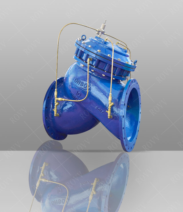
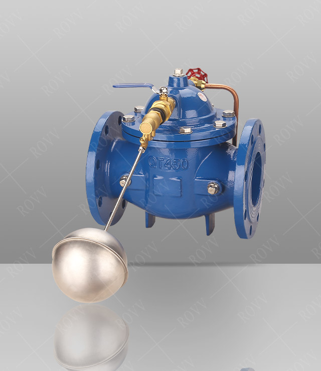
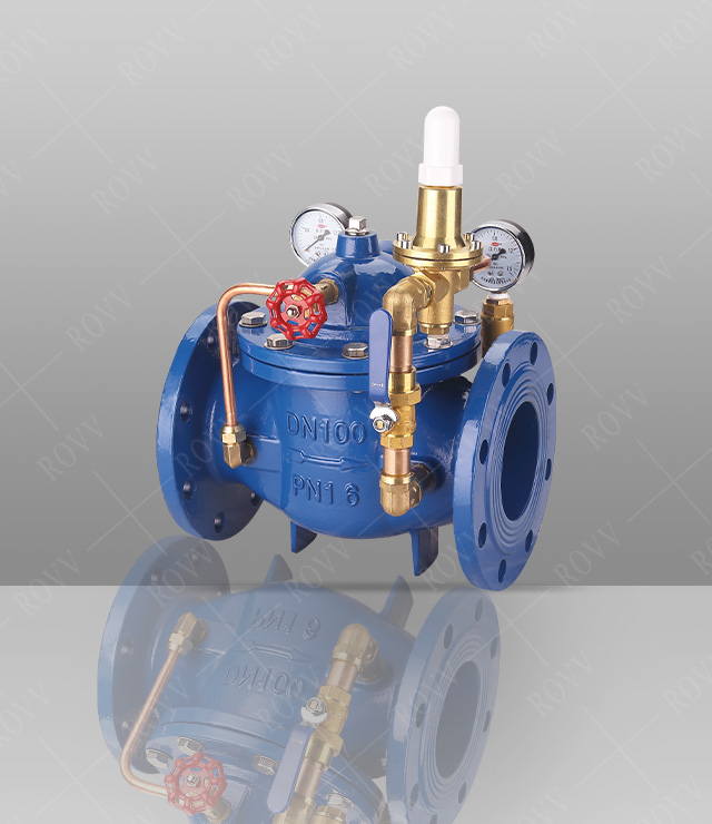
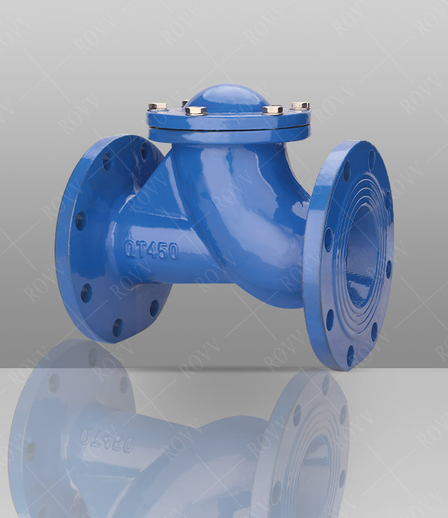
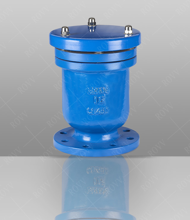
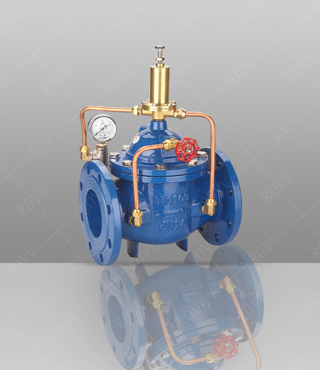
Multifunctional Water Pump Control Valve
Technical Parameters
Product model: JD745X
Nominal diameter: DN50~600mm
Nominal pressure: PN1.0~4.0MPa
Applicable temperature: 0°C~80°C
Applicable medium: water
Product Description
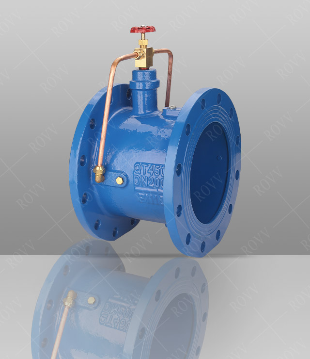
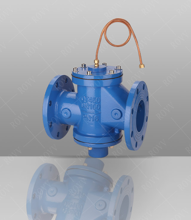
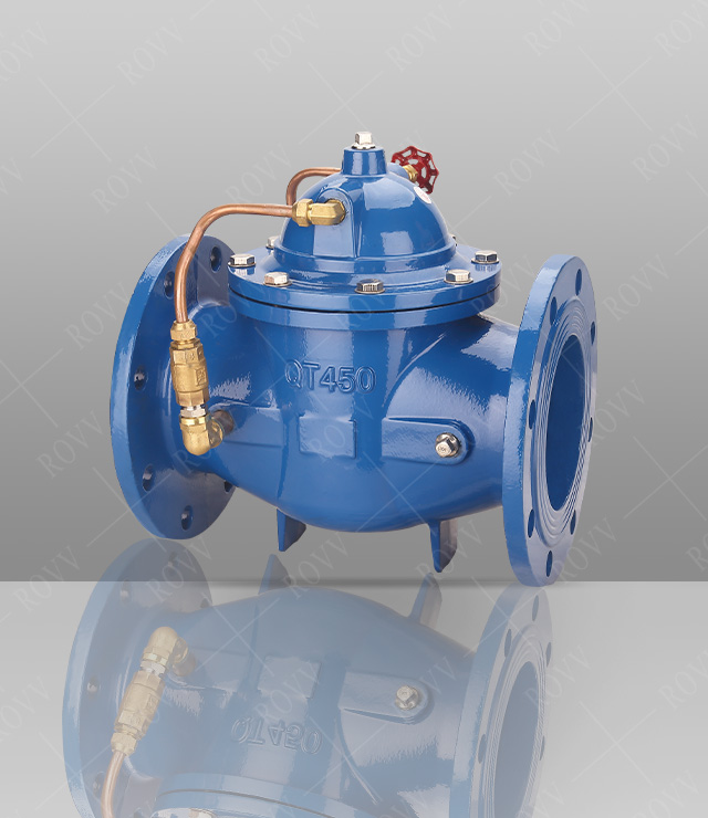
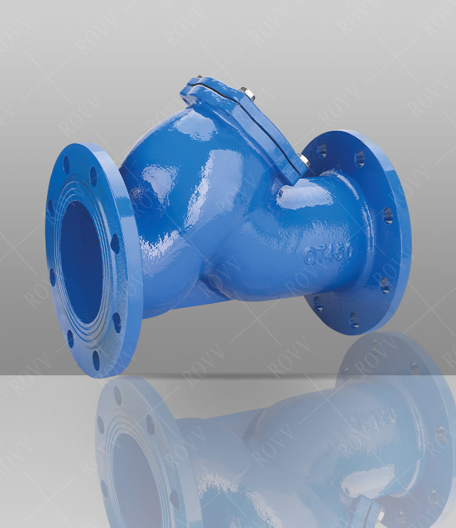
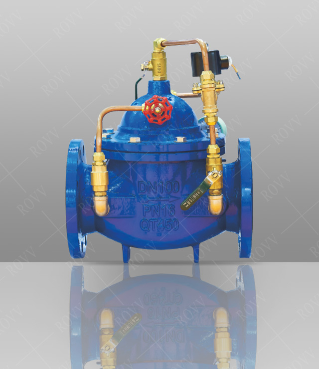
JD745X diaphragm multi-function water pump control valve is an intelligent valve installed at the pump outlet of high-rise building water supply system and other water supply systems to prevent medium backflow, water hammer and water hammer. The valve has three functions of electric valve, check valve and water hammer eliminator, which can effectively improve the safety and reliability of the water supply system. It integrates the technical principles of slow opening, quick closing and slow closing to eliminate water hammer to prevent the occurrence of water hammer when the pump is opened and when the pump is stopped. Just operate the pump motor opening and closing button, the valve can be automatically opened and closed according to the pump operation rules, with large flow and small pressure loss. Diaphragm type is suitable for valves below DN600mm.
Working Principle
When the water pump is started, the water pressure acts on the lower part of the main valve disc and the lower chamber of the control chamber. This pressure causes the main valve to open. The water in the upper chamber of the control chamber is slowly discharged to the outlet through the regulating valve B, and the main valve is slowly opened. . By setting the opening degree of the regulating valve, an appropriate opening speed of the main valve can be obtained.
When the water pump stops working, the water pressure at the inlet drops rapidly, and most of the openings are quickly closed under the action of self-weight and spring pressure, preventing the water from flowing backwards. It closes slowly at the bottom, and the closing speed is slowed down to form a buffer to prevent the pressure from increasing sharply.
The opening and closing speed of the valve can be obtained by setting the opening and opening ratio of regulating valves A and B.
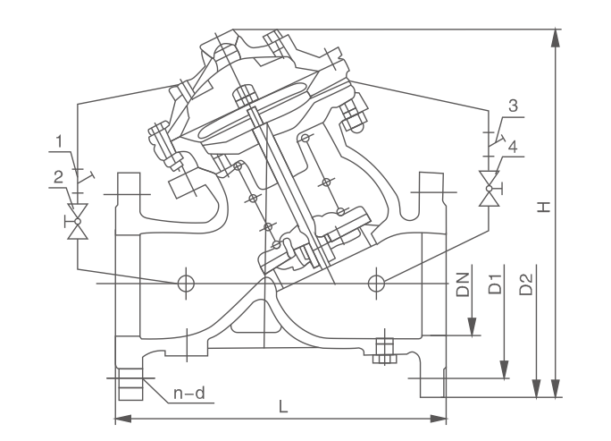
Main External Connection Dimensions
|
DN |
50 |
65 |
80 |
100 |
125 |
150 |
200 |
250 |
300 |
350 |
400 |
450 |
500 |
600 |
|
L |
203 |
216 |
250 |
320 |
365 |
415 |
500 |
605 |
698 |
787 |
914 |
978 |
978 |
1150 |
|
H |
293 |
328 |
364 |
418 |
481 |
543 |
673 |
729 |
927 |
957 |
1188 |
1218 |
1256 |
1600 |


